Sunday, March 30, 2014

Kinematics: Types of joints continued

First Order Pin Joints: This type of joints have two or more Links and are said to be of Order One less than the Number of Links joined. 


In the above Fig. you can notice there are two links joined by a pin, therefore, the Order of the joint is First. The Degree of Freedom i.e. DOF = One 


Second Order Pin Joint: In this type of joint there are there links joined by a pin. Since the number of Links is three the Order (of the joint will be one less than three) is said to be Second Order


In the Fig., posted above, you can see if Link L1 is taken as the reference Link then the other two Links L2 and L3 will rotate, (with respect to L1 as shown in the Fig.) the Degree of Freedom i.e. DOF = Two


A Roller on A Plane: This is an example of Higher pair. The pair is entirely different type of pair (joint). You can see in the Fig. posted below, that the Roller is simply placed on a plane without being joined by a pin or a slot, but is in contact with the plane. 


There are three kinds of possible motions in such joints (pairs), the Roller can simply Roll Or can Slide Or can Roll and Slide, over the plane depending on the friction between roller and the plane. The DOF is either One or Two. When the Roller only rolls the DOF = 1, when it only slides DOF = 1 and when it rolls and slide at the same time the DOF = 2.


Saturday, March 29, 2014

Kinematic Joints: Types explained with images

Rotating full Pin type Joint: In the Fig. posted below there are two Links joined by a pin. The links can have only rotational movement with respect to each other. In this type of joint the Degree of Freedom  is one. This is a Lower pair. 


Translating Slider: You can see in the Fig. posted below that the Slider can move only inside the slot, along the 'x' axis .This type of joints are known as Translating full slider. This type of joint falls under the category of a lower pair. The joint has one Degree of freedom. 


Link against Plane: This type of joint falls under the higher pair category. This is an example of  a joint which has Two degrees of Freedom. By looking at the diagram one can understand that it can move along 'x' Axis and rotate too. 


Pin in Slot: In the diagram, posted below,you can see that the link is connected to the slot by means of a pin. It is evident that the slot will permit movement along 'x' Axis, the link is free to rotate also. The joint, therefore, has Two Degrees of Freedom.It falls under the higher pair category.


Friday, March 28, 2014

Types of Joints - Pictorial views: Their Degrees of Freedom


1. Rotational Type: The Fig. posted below shows the pictorial representation of a Rotational Joint. This joint has only One degree of Freedom. As you can see from the Fig. posted, the joint permits only rotational motion, shown by the arrow. It is constrained in the Axial-Directions. 


2. Sliding Type: The Fig., posted below, shows the pictorial representation of a Sliding joint. This joint has only One Degree of Freedom.You can see, the movement in just one direction is permitted. The arrows indicates that the inner square can move only axially, along - X-axis


3. Helical Type: The Fig.,posted below, shows the pictorial view of the Helical joint.  You may notice that the Screw is permitted to rotate. Although it moves in the linear direction, when it rotates, but it is not possible to push it axially. Therefore, it is said to possess only One degree of Freedom, shown by the arrow.


4. Cylindrical Type: The Fig., posted below, shows pictorial representation of a Cylindrical Joint. You can see that in this type of joint the shaft can rotate and slide along its center line too, as indicated by the arrows. It is, therefore, said to have Two Degrees of Freedom.


5. Spherical Type: The Fig., posted below is the pictorial representation  of the Spherical Joint. This is also known as a Ball & Socket joint. You may see that the pin connected to the ball can rotate around all the 3 - Axes i.e. 'X',  'Y' and  'Z'. Therefore, we call it a joint with Three Degrees of Freedom


6. Planar Type: The Fig., posted below, shows the pictorial representation of a Planar type joint  You may have noticed, in this case the block is free to slide along the 'X' and 'Y' Axes and also rotate around Z Axis, shown by the arrows. That is why this type also is said to have Three Degrees of Freedom.  


Thursday, March 27, 2014

Kinematic Chains: Inversions --- Part 3


The Third Inversion more examples:

One of the most interesting application of Third-Inversion is the Rotary-Engine of an Air-Craft, shown in the Fig. posted below;


In case of the Rotary-Engines, the crank, item -2 in the fig, is fixed to the frame ----- and the propeller was attached to the rotating  crank-case. Now a days the use of rotary-engines has drastically reduced owing to the advent of Jet-Engines ---- which are faster, have better fuel economy and are more reliable. You may be aware this type of engines were extensively used in World-War- I.

Fourth-Inversion: 

In the Fourth-Inversion the slider is fixed, as shown is the diagram posted below;


The very commonly used application of fourth inversion is a Hand-Operated Pump, shown below;


Wednesday, March 26, 2014

Kinematic Chains: Inversions - Part-2

3. Inversion - Third type: 

The Third-Inversion is done by fixing the Crank- as shown in the Fig. below. This is an inversion of Slider-Crank mechanism, you may recall, was discussed while discussing  Grashof-type-Chains.


This is the inversion on which Whitworth-Quick-Return-Mechanism is based on.The Whitworth-mechanism is widely used in Shaping-Machines. In this inversion the Link-3, of the Fig. below, is the Driver which rotates at a uniform angular velocity. and makes the Rocker oscillate.  The point 'D' of the Rocker is connected to the Ram with the help of Link-5. As the Rocker moves back and forth it moves the slider back and forth too. 


Tuesday, March 25, 2014

Kinematic Chains: Inversions

Inversions of Kinematic Chains:


In the earlier posts it was stated that a mechanism is a Kinematic Chain  having one link fixed -- and also that a chain with 'N' number of links would result in 'N' number of mechanisms. It was also discussed that 

  • a non-Grashof chain would give us 4 Nos. of Double Double-Rocker mechanisms and 
  • a Grashof chain would give us two Crank-Rocker mechanisms, a Double Crank mechanism,  and a Double-Rocker mechanism. 
Out of all the above mechanisms it would be useful to consider the inversion of Slider-Crank mechanism only, since it gives you some extremely useful mechanisms for practical applications. 

1. Inversion of First type: 

We will try to understand the first inversion by means of a diagram, posted below;


As you may observe, the Fig. this shows one of the most common applications of the first inversion. Can you identify, from the Fig. which is the application we are talking about?  We are talking about;
  1. Steam Engines.
  2. Internal Combustion Engines i.e. Car Engines.
In both the cases the Piston '4' is the driver which make the Crank '2' rotate by repeatedly pushing-and-withdrawing-action on the crank.

2. Inversion of Second Type:

In this type of inversion you can see, from the Fig. posted below, the connecting rod '3' is fixed and the Link-'4' oscillates. 


This is a unique arrangement and is used in some of the Steam-Engines  since it permits the use of simple ports, instead of the complicated valves, for steam inlet and outlet. One more very useful applications of second-inversion is  the Quick-Return portion of the Crank-Shaper mechanism, shown below;


In case of this arrangement the rotation of the Crank '2' is translated into a slow Working -Stroke and a Quick-Return of the Ram.

Note: Please  post your comments and share the post.
Thanks

Monday, March 24, 2014

Linkage: Velocity Analysis and Kennedy's Theorem

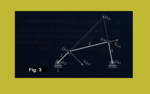
In the preceding post, the Instant Centers had been explainedLet us bring back the Fig. 3, of the last post, to recapitulate the method of determination of instant centers: 


Kennedy's Theorem: Also known as law of three centers, states that:

"If any three bodies 1, 2, and 3 have plane motion, their instant centers Q12, O13 and O23 must lie on a straight line" 

(The above Fig. shows how the method of applying notation works) 

In order to understand the theorem you will make use of Fig. 4, posted below:


The statement itself provides a ready basis for locating all the instant centers in any mechanism. 

Making use of the theorem to locate the Instant Centers:

You will appreciate that every link in a mechanism has an instant center with respect to every other link. Since, each instant center involves two links (in the previous post it has been seen that the order of positioning of the links is not important), we may say that the number of Instant Centers 'n' will be the number of possible combinations of 'N' links, taken two at a time. Therefore, we can express it in equation form as under:

n = N(N-1)/2

Once the number of instant centers is determined you may use some system to list all the centers. Thereafter, the easily recognized centers are identified and the Kennedy's theorem is applied for locating the remaining instant centers. 

P.S. Please post your valued comments and also share the Blog with your friends. 
Thanks

Sunday, March 23, 2014

Linkages: Velocity Analysis by Instant centre method

Concept of Instant Centers:
The method of Instant centers is one of the easiest means of determination of the velocity of a point in a mechanism. It is based upon the assumption that at any given instant the motion of one body, with respect to another body, is such that there is a 'point', in the plane of motion, where the two bodies have no relative velocity. This point may or may not lie on the actual links, it may even be at infinity

Note: The picture will become clear after you go through the whole post and come back to revisit the above statement.

Further, you may try to understand that since there is no relative velocity between the points, therefore, at this point both the bodies must have the same absolute velocity. 

You may appreciate that the other points (other than the 'point' discussed above) on the bodies do not have zero relative velocity(ies). Also, since the links are rigid bodies, the relative velocities are because of the relative rotation about a common point. 

The 'point' in fact represents the instantaneous axis of rotation of one link with respect to the other. This point is known as the instant center or velocity pole or centro

The best way to understand any statement in engineering is by using a sketch or a diagram. 


We take up Fig. 1 first. From the Fig. 1, you may notice that the link-2 can only rotate with respect to the fixed link-1, around point O21. Please note that the notation O21 indicates the instant center of rotation of link-2 relative to link-1

Here, O21 doesn't have any motion, hence is called the Fixed Center. Now, for any point on the link-2 the direction of rotation is perpendicular to it. The magnitude of the velocity is is proportional to the radius from the center O21.

Next, we take up Fig. 2. In this case the fixed centers are O21 and O41. The instant center of rotation of link-3 relative to link-2 will be at the point O32, the point at which the two are mechanically connected. Another point to be noted is that O32 could also be considered as the instant center of link-2 relative to link-3. Similarly the other point is O34 is also an instant center. You may take a note of the fact that because the center O32 has come into existence due to the mechanical connection between link-3 and link-2, as such its position with respect to either Link-2 or link-3 remains unchanged, it may be called the permanent center

You may appreciate that it is always possible, and is also easy, to identify the permanent centers by merely looking at the diagram. The method proves to be useful because of the fact that the links having complicated motion, such as link-3, have instant centers, relative to the members they are mechanically connected to and also have instant centers, relative to all the other members in the mechanism. Moreover, it can be seen that the instant center O31 is of great importance because (considering the velocities) it is the center of rotation of link-3 with respect to link-1. 

In the preceding post you have already seen that the velocity of any point on a link is proportional to the distance from the point to the center of the link's rotation relative to the ground. Therefore, if the velocity of any point on link-3 and the location of the instant center O31 are known, the velocities of all the points on link-3 can be determined by drawing similar triangles which gives the desired proportional relationships. 

Now, our real problem at this point is to locate the center O31. This brings us to Fig. 3 posted below: 


The procedure of finding O31 is shown in the Fig. 3. The centers O32 and O34 have velocities perpendicular to the link-2 and Link-4 respectively. As such if O32 and O34 are considered as pints on link-3, the instant center of rotation of link-3, relative to the ground will lie on the lines which are perpendicular to the velocities of O32 and O34; thus it is an extensions of the lines O21-O34 and O41-O34 which intersect at O31. 

P.S. Your views and comments are solicited, please don't forget to share if you find the post interesting and worth sharing!!!

Saturday, March 22, 2014

Linkages: Velocity Analysis basics

Why the Velocity Analysis is required:

In the past few posts we have talked about the geometry of some of the mechanisms. When we go for designing a mechanism, which will be a part of a machine, the mere knowledge of geometry is not enough. We all know that machines are required for doing a specific work, which is not possible without the motion of the mechanisms, that are a part of the machine.
Consequently, the analysis and calculation of motion, of the mechanisms, is a prerequisite to designing. 
The simplest method of analysis is to pick a point in the mechanism and write down the equation of displacement of the point as a function of time. There are difficulties in formulating simple equations for all the mechanisms, except the Crank & Slider and some of its variants. One has to take the help of some kind of Vector Analysis. Some of the commonly used methods will be discussed.

Finding linear velocities by Composition and resolution:


The mechanism, shown above, is a Four-Bar mechanism in which the Driver Link-2 is transmitting motion to Link-4. The pin connected, intermediate link-3 is capable of transmitting motion or force either under tension or compression, therefore the line of transmission must lie on Link-3. 
Suppose, the driver has an angular velocity of ω2 in a anticlockwise direction, then point 'A', will have velocity (with respect to the fixed link) equal to the Vector AM2, which is equal, in magnitude, to O2Aω2. The component of this velocity, which actually drives the mechanism, AS2 lies along the Link-3. Since the Link-3 is rigid, point 'B' will have the same component of velocity - (BS4 = AS2). Considering that the Link-4 is constrained to rotate about point O4 and the velocity of point 'B' must be perpendicular to link-4 and the magnitude, that it has, a component BS4 along Link-3. The required velocity of point 'B' as given by the Vector BM4. 
Further we have the angular velocity  expressed as;


ω = V/R

Where ω = angular velocity
           V = absolute Velocity of a point on the body 
           R = radius from the centre of rotation

Therefore, we have;
  
 ω2 = AM2/O2A   and also  ω4 =  BM4/O4B


The ratio  ω2/ω4 =  AM4/O2A x O4B/BM4

The line O2F2 and O4F4 pass though the centres of ration O2 and O4 respectively. These are also perpendicular to the line of transmission.
Further, the triangles O2AF2 and AM2S2 are similar, since the corresponding sides are perpendicular. The same applies to treiangles O4BF4 and BM4S4, also the triangles LO2F2 and LO4F4 are similar.
Now, by proper substitution, the ratio equation can be written as :

ω2/ω4  = O4F4/O2F2

and also

ω2/ω4 = O4L/O2L

The relationship expressed by the above equations is called the Angular Velocity Theorem, which is stated as:

The angular velocities of the driver and the follower are inversely proportional to the length of the perpendiculars from the centres of rotation to the line of transmission OR inversely as the segments into which the line of centres is cut by the centre line of transmission.  

Friday, March 21, 2014

Improvised Machining: Mechanism for machining circular surfaces on a Planing Machine.


Mechanism devised for machining of Inner circular surface:

There are challenges one must face in order to be successful in one's profession. The mechanism, being shown in the video clip, is a an outcome of successfully overcoming one such challenge.
Watch the video closely, you will find a curved inner surface being machined, on a conventional Planing Machine. 


The item being machined is a huge circular coupling, weighing approximately 1000 kgs. The inside of the coupling has two straight surfaces parallel to each other and two curved (arc of a circle) surfaces parallel to each other. The Flat surfaces are at right angles to the circular surfaces. 
The tool post of the Planing machine has been modified to rotate around an axis. This mechanism has been totally designed and developed by your author, the people who have assisted in fabrication, machining and the fitting work have done an excellent job and made the mechanism a great success. 
The details of the mechanism are not being shared because of the pending design-patent. Please watch the video and write in to me should you have any questions. You can reach me at sunilmcg@gmail.com. 

Thursday, March 20, 2014

Kinematics: Higher and Lower pair types, also difference between Chain & Mechanism

Kinematic Pairs -- types:

A Kinematic pair comprising two contagious (ability to transmit) links are classified into two categories: 

  • Lower Pair: These are kinematic pairs having sliding joints which are in surface to surface contact e.g. shaft & bush
  • Higher Pair: These are kinematic pairs having either linear contact e.g. cam & follower OR are in point contact e.g. pivot on a plate


In the above Fig. two different types of joints have been shown and the third one is the combination of the first two. The symbol representing these three are also shown below each.

Some more basics of Kinematics are depicted in the Fig. below along with the description:


Degree of Freedom of a mechanism:

One of the important concepts of Kinematics is to define the degree of freedom of the mechanism.It is defined by Grubler's Equation, which can be written as follow;

F = 3(n-1) - 2g

Where, F is the degree of Freedom, 'n' is the number of links (including the fixed link), 'g' represents the number of joints. We may say 'F' is a function of 'n' and g''. 

Capability of rotation in  Four-Bar Linkages:

In a four-bar linkage only the shortest link has the capability to rotate, as per Grashof's rule. The only exception being a double crank and double rocker mechanism. 

Wednesday, March 19, 2014

Kinematics: Grashof Linkage - Two situations;

You may recall the definition of Grashof-Linkage, which states that the sum of the lengths of the shortest and the longest Link is less than or equal to the the sum of the lengths of the remaining two links, let's take up both the cases one by one.  

Let us take the case of the Grashof Linkage where the sum of the lengths of the shortest and the longest Link is less than the sum of the length of the other two sides.


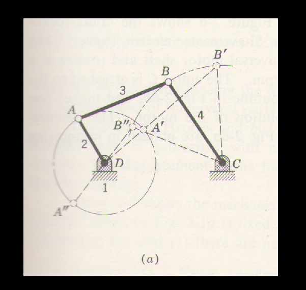
In the Fig., posted above, The limiting phases of the four-bar Grashof linkage are shown. In these cases the fourth link has been formed, as can be seen, by fixing one to the links adjacent to the shortest link. Refer to Fig. (a) the sum of the shortest and the longest links is less than the sum of the other two sides.

The formation of the linkage in Fig.(b) is similar to that of Fig.(a) except that the length of the linkage CD has been increased. 


In Fig.(b). you can see that the sum of the length of the shortest and the longest links is equal to the sum of the lengths of the other two sides.   

Both the linkages, mentioned above, have drivers (link 2) that rotates to make the follower link(4) oscillate, as such both fall in the category of Crank-rocker mechanisms, but there is some difference between the two.  

The mechanism of Fig.(a) has a driver 'without' a dead-centre-phase (look at the position of joint at position A') whereas, in Fib.(b) we have a dead-centre-phase with A and B in simultaneous dead-centre-positions at A" and B" respectively.   

The important point to note, therefore, is that at the simultaneous dead-centre-positions for links 2 and 4 are not totally constrained. It means that they are capable of rotating either way. Because of this the direction of rotation can change at A" and B". These points are, therefore, called change points. 

Tuesday, March 18, 2014

Kinematics: Linkages Non-Grashof, Analysis

Analysis of Non-Grashof Linkages:

In the figure, posted below, a four-bar Non-Grashof Linkage is shown. The same will be analysed and we will see what are it's limitations. There will be four Limiting phases in this type of Linkages, all the four, for this specific figure have been drawn on a Solid Edge Cad-software and are to the scale. The dark lines are that of the Linkage at rest and the dotted lines show the four positions of the linkage as it moves. 


From the figure it can be seen when point A moves through the Arc A1A2A3A4 and comes back at A1, point B moves through Arc B1B2B3B4 and comes back to B1. It can also be seen that when A is at point A1 or A4 the links 3 and 4 become collinear there is a phase of non-rotation i.e. the link 2 comes to a standstill position, unable to move the combination of Link3 and Link4 (since they are lying in a straight line). Under the circumstances, when link-2 is in a position where it can neither rotate clockwise nor anti-clockwise the position is known as a Dead Centre Phase. Similarly point B also has two Dead-Centre-Phases

In order to understand the meaning of the Dead-Centre-Phase, let's try to bring in the issue of transmission of load, which is what all linkages are required to do in practical applications. 

Assuming that there is no frictional loss, the effect of inertia and acceleration are also being omitted to simplify the matter. It is noteworthy that link-3 is a two-force member and transmits force between A and B only in tension or compression. Considering Link-2 to be the driver and link-4 to be the follower, if the Link-4 is to be driven clockwise against torque T4 then for equilibrium of link-4, the sum of torque about point C should be = 0. The equation of force F34 (force acting on point B in anticlockwise direction) 

F34 = T4/ h = T4/CB x Sinδ

Where F34 = magnitude of force exerted by Link-3 on link-4  

From the equation, above, it can be seen, for a given magnitude of force T4, the force acting at A, at B and along the link-3 will be minimum when δ = 90°and will increase as δ decreases, thus becoming infinite when δ = 0°. 

The angle δ (when acute) the angle between the line of the action of force on the driven link (F34) and the line of hinges (CB) is known as the angle of transmission

It can be seen, the angle of transmission become = 0 when the links are at dead-centre-phases. As such it is not a desirable phase in most of the mechanisms. 

In the next section the Grashof Linkage will be analysed and you will be able to make a distinction between the two vis-a-vis their usages.  

Sunday, March 16, 2014

Car Engine: Crankshaft, piston rod and piston Mechanism

Applications of Four-Bar-Linkage:

The four-bar-Linkage mechanisms have been discussed at length in the preceding posts. It's time to see how these have been used for driving various machines. 


Explanation:

Suppose the follower of a four-bar-linkage is made infinitely long, what will happen ------- in such an event, a point on the Axis of the pair, joining the connecting link to the follower, would move back and forth in a linear motion. In a practical application the follower becomes a Sliding-Block or a Piston. In both cases, namely, Sliding-Block or Piston, both have a constrained to move is a straight line by a guide or a cylinder respectively. 

If we use Grashof-Linkage (shown above), in which one of the links adjacent to the shortest link is fixed (in the above Fig. the link AD of the Grashof chain is fixed), the mechanism thus formed is a Slider-Crank-Mechanism. Please see the Fig. posted hereunder: 

Applications of the Piston-Crank-mechanism is widely found in the Diesel and petrol engines. The outline-diagram of the 'V' Block Engine is posted below. Please look at the arrangement and compare it with the arrangement used in the 'V'-Block diesel engines.


We will try to understand the hypothesis of infinitely long follower with further clarity in subsequent post.

Saturday, March 15, 2014

Project work: How to Design a Drag Link Mechanism


Step 1: How to determine the sizes of Links in Drag-Link Mechanism:

In this section you will learn to actually make a 'to the scale drawing' of a Drag-Link Mechanism. If you have to design a Drag-Link-Mechanism your first step will be, to find the sizes of the linkage in order to ensure that the mechanism really works. Choosing arbitrary sizes will land you in soup and your mechanism may get stuck. This can also be used for project-work, whereby you can design the mechanism and demonstrate how it functions. The 'to-the-scale-dimensioned-drawing' of the mechanism is being posted below. The steps of construction are being articulated below the drawing:


Note: As you can see, sample dimensions have been assumed for making the above 'Drawing'.

In the Drawing, you can see, there are two circles. At first draw a centre-line almost at the centre of the drawing sheet. On the centre line draw the large circle having radius = 90mm, followed by another circle of radius = 75mm. The centre distance between the two circles has been chosen = 30mm (you are free to choose as you wish, later on, but in this case stick to the sizes shown). Now draw the line DC" (it lies on the centreline) next draw the line AB" followed by joining the ends B" and C" to get the length B"C" which is = 95.79 mm (found out by joining points B" to C" and measuring the length).
It is noteworthy that we have chosen to draw the lines DC", AB" and B"C" before drawing AB, BC and CD because we have to determine the length B"C" (key to the problem) since this the correct way of finding the length of BC which is same as B'C' or B"C".
Having determined the length B"C" you can go ahead and draw AB ( keeping the slant similar to the drawing) followed by drawing BC = 95.79  and finally joining C with point D.  
For the next position of the of the linkage, take a lengths of 95.79mm and then with point C' as centre draw an arc cutting the smaller circle, the point of intersection gives you point B', join B' and C' to get B'C' = 95.79mm. Thereafter join B' to D to complete the drawing.
Having completed the drawing, measure the angle between AB' and AB" = β on the right of point A followed by measuring the angle between the same two lines on the left of point A = α 

You will find that  α > β 

Having completed the exercise we will go back to the post where a similar (undimensioned) diagram was posted to explain the principles behind the functioning of a Drag-Link mechanism and try to understand the same.

When Link-2 acts as the driver, rotating at a uniform speed, we will have Link-4 (the driven) moving at a non-uniform speed. 

Explanation:

Suppose, starting from point C', the point, moves through an arc C'CC", i.e. the Link-4 rotates by 180° whereas the Link-2 rotates through an angle = α. 

Next, the Link-4 keeps rotating from point C" and covers another 180° till point C', this time Link-2 rotates through an angle = β. 

You have already measured both the angles and seen for yourself that β is much smaller than α. 

As a result, it is evident that for the same amount of rotation of Link-4, rotating at a uniform speed, in the first-half covers first 180° and the second half covers second 180° ---- the 'follower'  i.e. Link-2 takes much smaller time to go through the second half of rotation as compared to the first half. 

Note: On the other hand if Link-2 becomes the driver and Link-4 the follower the situation will be the opposite.